|
|||||||||||||||||||||
|
|
|
|||||||||||||||||||||
|
|
|
|
||||||||||||||||||||||||||||||||||||||||||||||
|
Hello, fellow modelers and readers!
Despite these shortcomings, a very good model can be made out of this kit with patience and a little extra effort.
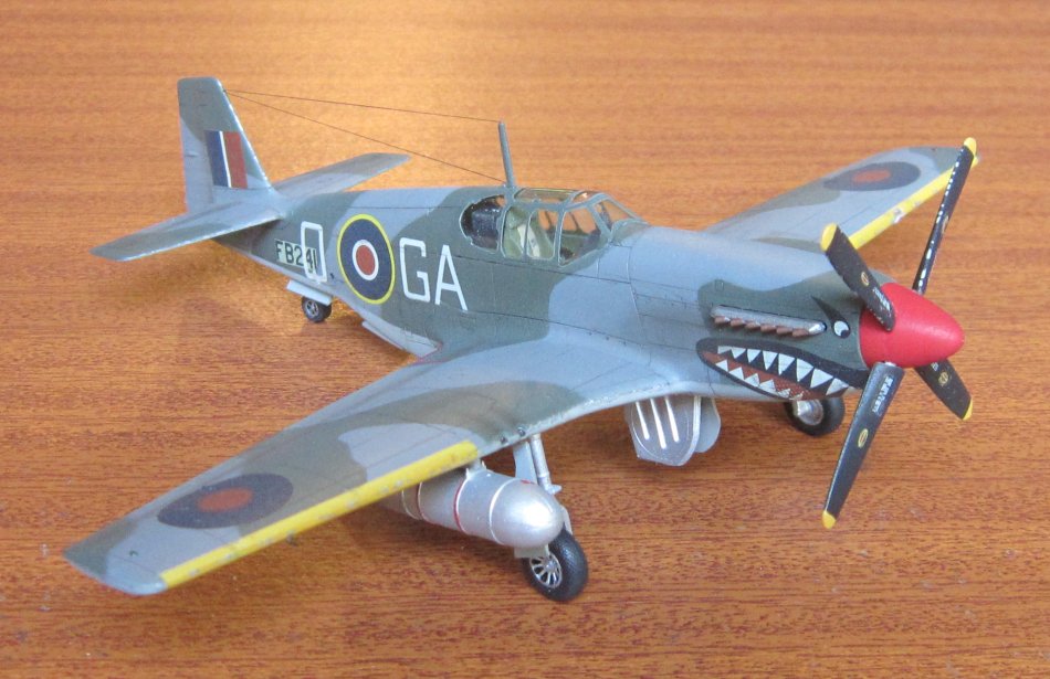
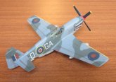
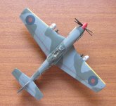
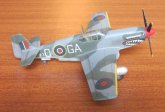
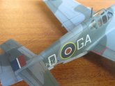
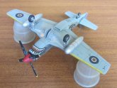
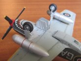
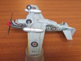
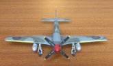
Two options of exhausts are provided, one for each painting option, which are designed to be glued from the inside before joining the fuselage halves. I used the ones that correspond to the aircraft I chose to build, however, the exhausts don't protrude enough from the fuselage surface, IMHO. Regrettably I noticed that after I joined the fuselage halves. To fix this problem, I scraped the exhausts the best that I could, modified the other set of exhausts so that they could be attached from the outside, and glued them over the previous exhausts, flush with the fuselage. There were also problems with the painting of the aircraft camouflage patterns. I noticed that the lines that separate the Ocean Grey from the Dark Green on the kit's top view painting diagram doesn't match the ones from the port and starboard fuselage sides. In my first attempt I modified the lines to force the matching and painted the model this way, but I wasn't satisfied with the result. Later I decided to search for a "correct" diagram on the Internet. I found photos of several finished models of the aircraft I was building (GA-Q from the 112 RAF squadron,) and also found that there are noticeable differences between them. Then I searched for the instruction sheet of the 1-48 scale Mustang III from Tamiya, which include the same aircraft. Comparing the painting diagrams of my Hasegawa kit with the ones of the Tamiya kit I encountered more differences than I expected, specially on the top of the port main wing and on the top of the starboard stabilizer. Even the serial numbers are different! The Tamiya kit also indicates that each main wing leading edge had a yellow band (supplied as decals) that are absent in the Hasegawa painting diagram and decal sheet, as are the wing walks commonly seen on Mustangs. As there's no way to know which set of painting diagrams is "correct," I decided to keep some areas according to the Hasegawa diagrams and changed others to match the Tamiya diagrams, including the addition of painted yellow leading edge bands and scratchbuilt wing walk decals. While painting the model again I accidentally lost the antenna mast, so I scratchbuilt a new one and gave it a more "normal" shape, with its bottom wider than its top, also trying to make the rear leading edge thinner than the front one.
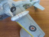
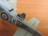
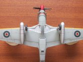
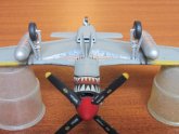
As I also noticed that some of the kit's panel lines virtually disappeared under the paint, I rescribed some panel lines again and decided not to apply more paint to the model other than the neccessary gloss and clear coats. The weathering therefore was limited to the application of exhaust smudges, dirt and paint chipping. I also highlighted the panel lines and rivets with an enamel wash. The kit had two optional pairs of drop tanks as underwing stores, no bombs were included. I chose the big 108 gallon drop tanks as underwing stores. The painting of these drop tanks deserve to be mentioned. As I know that the real size ones were made from compressed paper, I never imagined that their color was aluminium. The kit's instructions doesn't mention anything, so I first painted them with the underside color of the aircraft. When I searched photographs of models of Mustangs I found that almost always the 108 gallon drop tanks were painted with aluminium. Therefore I searched wartime photographs of the subject, and I confirmed that the color was a rather dull aluminium, and I also found that they had two parallel red bands right below their attachment points, so I painted them carefully with a very small brush. Another source of confusion was the antenna wires. Neither Tamiya nor Hasegawa kit's instructions specify where antenna wires, if any, should be attached. Many photographs of finished Mustang models don't include any wire. Hasegawa kit's box art has a wire drawn from the canopy ceiling, just after the antenna mast, to the top of the fin's leading edge. In the beginning I thought to reproduce it and drilled a small hole on top of the cockpit canopy where to insert and cement the wire. Later I looked for profile drawings of the aircraft, and I found a pair of them that caught my attention. Both of these drawings show the aircraft with two antenna wires, the one that I previously described and other that goes from the top of the mast to the same point on the leading edge on the fin. I also found that the wire attached to the top of the canopy is in fact attached to a small protuberance that, fortunately, was molded over the kit's canopy, so the hole I previously drilled was unnecessary and I had to fill it with CA glue. My antenna wires were made with a single 12 cm segment of black human hair, on which I made a knot in the middle. I later bent the hair at the point where the knot was, glued the knot to the fin and the extremes to their attachment points over the mast and on top of the canopy. In the end I don't know if these wires are correct, but what really matters to me is that they add a lot to the look of the finished model, of which I'm very pleased. Thanks for watching and reading. Orlando Sucre Rosales
|
|||||||||||||||||||||||||||||||||||||||||||||||
Photos and text © by Orlando Sucre Rosales