|
De Havilland DH-110
History
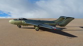
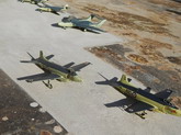
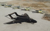
The DH-110 was designed originally to an RAF requirement for a night and all-weather fighter that was later fulfilled by the Gloster Javelin. Later the DH-110 prototypes were ‘navalised’ and the type was adopted by the Royal Navy in a similar role. The kit provides for the second prototype aircraft (WG240) at the time of the Farnborough Air Show in September 1952 when it was finished overall gloss black with white serials on booms and under wings.
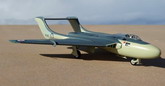
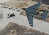
The pilot’s cockpit was offset to port to provide sufficient working space for the radar operator/navigator below and behind on the starboard side. Radar equipment included hydraulically driven scanner in a fibreglass radome in the nose.
The first prototype WG236 flew for 46 minutes at Hatfield on September 26th 1951 piloted by John Cunningham and first exceeded the speed of sound in a shallow dive on April 9th 1952. The second prototype WG240 flew on July 25th of that year.
On September 6th this aircraft went unserviceable and the first prototype aircraft WG236 was substituted in the air display, flown by John Derry and his test observer Tony Richards. Both crewmembers were killed when WG236 broke up in flight during a demonstration following a catastrophic wing failure. The effect of extreme acceleration and sharp roll at low level caused the aircraft to break up in air over the watching crowd. Also losing their life were 29 spectators and many others were injured when one of the engines still burning flew into the crowd–line. Ambulance, fire and rescue service were quickly on the scene and luckily the crowd did not panic. WG240 was grounded until did not fly again until June 11, 1954 after structural modifications were made. These included an all-moving tail plane, cambered leading edge extension outboard of wing fences and reduced ventral fin area.
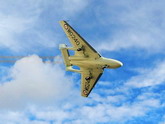
The design was developed into the Sea Vixen, which served with the Royal Navy from 1959 until mid-seventies. The DH-110 was the first twin-engined aircraft to exceed Mach1.
|
Click on
images below to see larger images
|
|
|
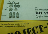
The kit: De Havilland DH-110 Kit PX-034
Type: prototype Naval all-weather fighter
Make: Project-X.Mantrack Hangar Productions
Cost: 12 Euro
Notes: vac-form with white metal parts and decal for the prototype DH-110
Scale: 1/72
The kit
This is a good kit, released in 1996 but had a few shortcomings particularly with engraved detail and fit of certain parts. However this is a clean and precise outline that is definitely an improvement over the only known early release of the Prototype DH-110 by Frog circa 60 years ago! There is no problem regards to overcoming the usual problem of tail sitting as the empty radome nose by itself offers ample of space, besides the two metal ejection seats located in the forward fuselage will assist matters. To remove any doubt and play safe I added lead weight to a forward nose compartment since the main gear is positioned forward in the wings. Better safe than sorry.
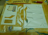
The kit is vac-form type in white soft styrene comprising 16 main parts as fuselage, wing parts etc and 10 minor parts as wing fences, wheel well doors, air intake items etc. Metal parts include wheels, oleo legs,
exhaust pipes and ejection seats. The main undercarriage is made up of 4 parts and that of the nose in 3, all accurate and detailed in all respects. The ejection seats are highly detailed and it is a pity that they are mostly hidden inside the two cockpits. Double A4 size instructions contain 1/72 scale plans and essential construction details. A nice front view will prove useful when fixing all parts as wings and tail plane indicating these are fixed level. A’ towel-rail’ aerial and wing tip aerials/tubes are made out of stretch sprue or metal wire.
Construction
As with every vac kit construction starts by scoring with a sharp knife around parts close to the edge of the mold parts. Parts are then bent and broken away from carrier sheet around score lines. Excess plastic is then sanded away on a wet and dry paper attached to a board. Fit of parts is checked before starting assembly. For the vac parts liquid cement as Humbrol brand or Revell liquid glue is used but when fixing metal parts then super glue would be required.
The fuselage parts were first prepared, cutting jet exhausts which were then filed to a circular shape, then wing root jet air intakes were cut and filed to shape. Pilot cockpit aperture in upper fuselage half was then cut. Observer’s side and top window cut and clear parts fitted to the observer’s compartment. Cockpit floor was made from scrap plastic with reference to the drawing supplied. Seats are painted and glued in place. Cockpit interior for both Observer and Pilot office, which is at a slightly higher level than the observer seat were painted and detailed.
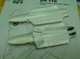
Air intake trunking was then cut and assembled. These are open-air intake shapes with a circular section at rear of trunking. The pair of air intakes is joined with a central web but I noticed that in order for the trunking align correctly inside the wings, these had to be separated and fitted each by itself. Instruction mentions fuselage bulkheads that may be misleading and was in fact referring to the trunking arrangement, which fitted in between wing roots and added strength. After checking for fit the wing halves were then closed and glued together. After setting overnight the wings were then drilled at their section so that two round holes fit into the fuselage sprue dowels added for the purpose to align and secure wings, these were followed by fixing the tail booms which were by now in two separate whole pieces. These had tongues to assist in achieving a strong bond with the rest of the wings.
After ensuring that the tail boom alignment is correct, the tail plane was then cemented into place between the two tail fins. Filler was then added to all joints. These were allowed to dry and sanded to finish shape. The rest of assembly was cementing the undercarriage legs, jet pipes and pitot tubes in place. Some slight alterations were made to the kit. These include cutting the rear of tips straight instead of pointed end., added fairing to upper of elevator root with tail booms., added crew figure to both observer seat and pilot seat and an appreciable quantity of filler was also needed to wing air intakes at bottom and top. The vac cockpit canopy was cut and fixed in place with Johnson’s Klear.
Color and markings
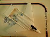
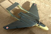
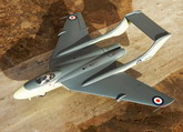
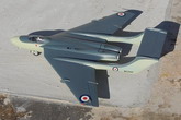
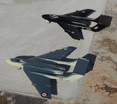
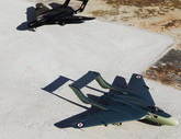
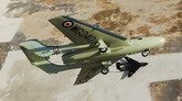
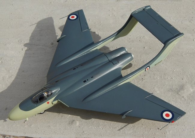
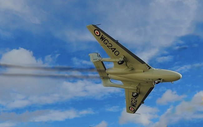
Kit provides markings for an all black WG240 but I went for the same aircraft at a later stage in service when it carried an early standard Royal Navy colors of extra dark sea grey upper surfaces and sky lower surfaces. Decals appear to be of high quality and I used the roundels provided on the decal sheet. The under wing serials were now black and I used an assortment from a Model Decal sheet.
Conclusion
Construction of this model was not as straight forward as it was thought to be at first since adjustments needed to be made all the way and probably more than one normally meet on a vac form kit. For example, two ‘stop’ inserts had to be added at rear of fuselage to prevent the metal exhaust parts from falling inside, and adding a small slot intake forward to main intake and other small items one meets as one moves along. In view of this I do not consider the kit as a good example for anyone who wants to make a start on vac kit building. In fact the title on the pack so states that the kit is for the experienced modeller. Still, anyone can take the challenge.
Ref:
Carmel J. Attard
|
Click on
images below to see larger images
|
|
|
|