|
I’ve pretty much covered the developmental history of
both the “E” and the “F” models in the previous kit reviews so I'm going
to get straight to the model. This project has been in the planning mode for
quite some time now. It was more than a year ago when I saw an Academy 1/72
B-17E done in Coastal Command colors that I decided I wanted to do one in 1/48.
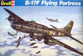
First I had to acquire a suitable starting kit since there was no “E” model
B-17 produced in 1/48. The Revell “F” was 90% of what I needed and I went to
e-bay for that. Actually I acquired two kits, one nearly mint and one that had
been started by a kid or novice modeler with a tube of Testors glue. I chose the
started kit as my base for the conversion and proceeded to disassemble it and
strip the brush painted layers off of it with Chameleon Paint Stripper.
This is only a starting point, I still needed a Paragon conversion set and
Paragon had already ceased production. I connected with another modeler in
Florida who had several Paragon kits in storage and was kind enough to part with
one. Things were moving ahead. I had to give some thought to final display and
long term storage for the model. Most of my shelf space is already filled with
single and twin engine aircraft and even if it were not, finding a piece of
shelf large enough to handle a 1/48 B-17 is always a challenge. Considering that
the interior of the Revell kit is already sparse I decided that this was going
to be built in flight, gear up. This definitely took the burden of scratch
building interior detail off my shoulders but replaced that with crew
considerations. I figured I would need at least six crewmembers on board: pilot
and copilot, both waist gunners, bombardier and tail gunner. These would be the
visible figures. From what I understand if you are so lucky as to acquire a
Pro-Modeler kit there are plenty of crewmembers included. This is not the case
so I will have to get creative. I’ll get back to the crew in a little while.
Decals are another consideration. I have plenty of
British markings in my spare decal stash but these are nearly all Spitfire or
Hurricane related, not nearly large enough for the heavy bomber. While I do have
a Lancaster in the stash I do not want to scavenge those decals. I searched
Great Models web store, Squadron.com and Eagle Strike Productions looking for
appropriate decals. Items of concern where obviously getting roundels of the
correct size but also a Scottish Coastal Command emblem. Not an easy combination
to acquire. Another question that has yet to be answered is whether or not the
roundel appears on the bottom side of the wing. I know that bombers operating
over the main continent do not carry these markings but that home defense
aircraft do. This aircraft fits into the home defense category so it may carry
them but I have not been able to verify it yet.
That search continues. I finally settled on a set from Aero
Master, Lancaster Bombers Part 2,
to provide my primary markings. I found a rough, black and white image of the
Scottish Coastal Command unit on-line that I’ve sent off to Mike Grant Designs
for a quote.
Although I do not have 100% of my materials gathered
I feel that I have enough on hand and enough in progress to start the kit. I’m
really anxious to play with those Paragon parts so that is where I’ll start.
The engine cowlings have a large casting block right on the nose. I used my
Dremel with a cut-off wheel to take off the majority of the material then
shifted to a sanding barrel to get down to the basic shape. From there an emery
board followed by a round diamond file and a few successively finer grades of
sandpaper finished off the cowlings.
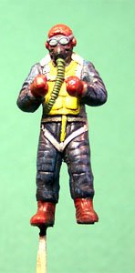
Resin dust is toxic so it is important to wear the
proper personal protective equipment (PPE) while sanding and sawing this stuff.
Pictured is the respirator that I’m using. I said “respirator” not
“mask”. A dust mask has a single elastic band to secure
it to your face while a respirator has two. This ensures that
the equipment is secure to your face and toxic particles are not slipping around
the edges and making their way into your lungs – a very important feature!
Now that I have satisfied (for the moment) the urge to play
with Paragon pieces maybe I can do some work on the kit parts. The conversion
directions call for installing the kit clear parts in both sides of the nose
then masking over them to create a third standard size window. This does not
look to be a good idea as the large window has a very pronounce rivet pattern
around it plus the window has a big freaking hole in it for a Browning machine
gun. I think that I will try a different approach. First, using a Xacto Leaf
blade I carefully trim off the rivet pattern. Next I cut pieces of Evergreen
stock sheet to fit the window openings and secure it with Tenex 7R. I putty the
inside to bring it to the same level as the rest of the fuselage and some putty
on the outside to cover any seams.
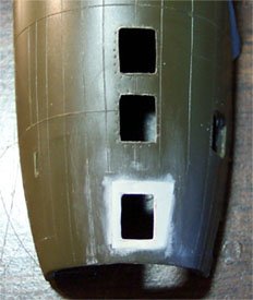
After my putty has dried overnight I sand both sides
smooth. When I applied my putty I used a Q-tip and acetone based fingernail
polish to smooth it out so the amount of sanding is minimal and there has been
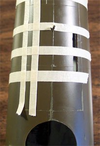
virtually no damage to the raised panel lines. Now I will lay down some strips
of masking tape to outline the dimensions of the new window. I use an archival
pen to trace the window edges then remove the tape. Next I use a small burr bit
in my Dremel to open up the window center. Once that is done I trim it close to
the pen line with a razor knife then shift to a small flat diamond file to
finish it off. This is done to both sides.
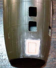
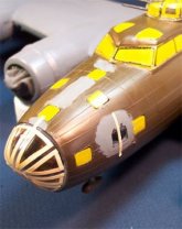
There is yet one more modification that has to be made to
the fuselage. I will be modeling an aircraft manufactured prior to the
introduction of the Sperry Ball turret. I will be installing a remotely
controlled turret and will need to install the sighting windows for the turret
operator. There are four small rectangular windows and a single dome window that
must be placed in the lower fuselage behind the belly turret position. The belly
gunner’s position is very close to the waist gunners’ positions, which must
have made this an extremely crowded area.
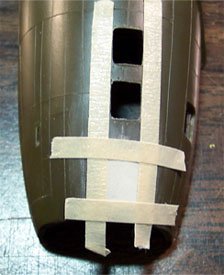
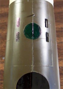
I’m starting with the right side fuselage and place my rectangular windows per
the Paragon instructions. I used strips of tape to outline them and followed the
same procedure as with the nose windows. Once the right side windows were
complete I taped the fuselage halves together and used more strips of tape to
place the left side windows. I also traced a 10mm circle on the belly with a
scribe in a compass for the dome window. I colored this area with a marker to
aid in cutting it out. The left side windows were cut out then I used a
cylindrical cutting burr to cut out the dome window then used some sandpaper to
clean it up.
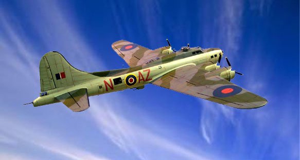
|
As I said before, this has been in the planning stages for some time. I knew
right from the beginning that I wanted to build this “in flight” with gear
up and now I must consider the changes that will be needed to accomplish this.
The gear bays are devoid of detail, which for my purposes is a good thing, less
stuff to get in the way. First thing I need to do is to get rid of the
retraction arm on the front of the gear strut. This would normally fold up and
just a small part would be visible from beneath the aircraft.
|
|
|
Folding the
strut and laying it in the bay would consume too much room however putting a
piece of Evergreen rod in the bay for just the visible portion works okay. With
the retraction arm removed I’ve placed the assembled wheel on the axel and
test fit it into the bay. Guess what, it does not fit. I have to open up the
hole in the interior bulkhead and trim the end of the axle to get it to fit into
the bay properly. The exterior opening needed a little sanding to allow the tire
to slide into position and I think it looks pretty good. The second bay is
treated in the same manner and now I can glue the bay bulkhead in place and
paint the interior Model Master Green Drab. |
| I know that a lot of B-17
instructions tell you to paint the interior chromate green but the truth of the
matter is that they were painted a variety of colors. Some were chromate green,
some were O.D. while others were dark olive, natural metal and in one case black
with messages written in white chalk from the production crew to the ultimate
flight crew. The bottom line was that the lack of the correct shade of paint was
not going to slow down bomber production by one second. |
|
|
Moving back to the fuselage, once again I have to consider “in flight”
options. Let’s take a look at that crew I mentioned earlier. The kit does not
include any crew so it’s scavenge time! I have an old Monogram B-24J junker
kit that I
got as an add-on to another deal and the seated pilot figure is still
inside the assembled fuselage as well as one standing figure – rip that thing
apart and salvage those two. I have a B-24D kit in the stash and steal the
seated pilot from that one. Now I have the pilot and copilot covered. Both
figures needed to have their butts shaved down a little with my trusty Dremel
and the bottoms of the boots had to be trimmed along with just a little off the
back to sit correctly. For the copilot I used a very small cutting burr and
removed the clipboard from his lap and rebuild his leg structure to give them a
little variety. They get mounted on toothpicks and painted for the job.
|
|
The interior of the fuselage gets a few coats of Green Drab also. The cockpit
assembly was completed per the instructions with the exception of the dash. I
found a spare B-17 dash decal in the spares bag (can you believe my luck?) and
put that on the dash. I glued the cockpit assembly in place on the right
fuselage half and then test fit the cabin roof with a pilot in place – nope,
not happening. The seats sit up way too high with the top of the headrest nearly
on the cabin roof and the pilots cap will not let the roof settle into place. I
check some in flight photos of real aircraft looking at pilots head position and
seat backs and my opinion is confirmed. I now cut out the seat assemblies, cut
about 1/16 of an inch off each seat leg and reinstall them. Now the pilots head
sits in the correct position.
That's two covered, four more to go. The next four are going to be more
difficult as they cannot stand upright nor be in a sitting position. I have to
look for some figures that I can cut up and reassemble into various crouched
positions. The tail gunner will be easy because I just need a bust for him. I
would like to have a least one waist gunner peering out the window and the other
moving about inside but still visible. I think I want the bombardier moving
forward into the nose position. Definitely have some work ahead of me.
Hold everything, change in plans. While I was searching for adequate figures to
slice up I got an email from modeling comrade Derwin who has 90% of a
Pro-Modeler B-17 crew set that he is not going to use. Well, I wasted no time in
letting him know I wanted those figures and he is mailing them to me so while I
wait for the arrival of the crew I will work on some other aspects of the kit. I
think I heard a collective sigh of relief from the spare figures box.
As I said before, this kit had been started by someone way back when and while
they had only done stuff to the fuselage as far as paint and glue the wings had
been removed from the sprue and when placed back in the box took some warpage. I
spent about an hour slowly stressing and gluing the wing halves together to take
the warp out of them and another hour after the glue (Tenex 7R) had dried
cleaning up the seam line on the leading edge. The fit at the engine nacelles is
not very good and there was a lot of carving and filling done around those
points. I still have to fill the exterior bomb rack mounting holes as those were
not present on the “E” model.
|
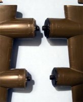
I feel that it’s time to play with some resin again and I’m taking a look at
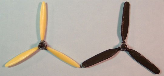
the propellers. The conversion directions call for the “F” model paddle
blades to be cut off the hubs and for the “E” model blades to be mounted in
their place. With four propellers to do and considering how fragile a prop is
once the blade has been removed and reglued I have some concerns about this. I
wonder if I would not be better off to simply try to sand down the kit blades. I
take out a set of the Paragon blades and look them over, it’s difficult to
compare them on the casting block so I slice one set of three apart for
examination. Look at the picture to the left and you can see what I’m talking
about. On the far left is the original cast of three blades from Paragon,
central is the kit propeller and on the right are the individual blades. They
look to be very nice castings so I will go to the trouble of removing them from
the block and replacing them.
|
|
Haul out the dust respirator and the Dremel and I’m ready to get
busy. I’m using the cut-off wheel to remove the majority of the casting block
from each blade leaving just a fine line of excess on each one. Once this has
been done to the first set of three I shift to a piece of 400 grit automotive
emery cloth and sand the excess material down until there is just the finest
line left. Now I change to a flat diamond file and finish the removal. From here
I use some very fine (800) sanding paper to polish the blade. One set of blades
equals about one hour of modeling time but the end result is three very nice
looking blades. Still have to cut the kit blades off and drill the hubs for
reattachment.
On the next set I change over from the cut-off wheel to a sanding drum and this
speeds up the process quite a bit. Now I am down to about a half an hour per
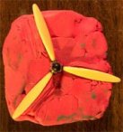
blade set. I still have to get these new blades on the old hubs. To achieve this
and maintain proper blade alignment for four sets I need a jig. I’m using a
block of modeling clay formed into a solid square, which I’ve gently pressed a
propeller into until the lower edges of the blades make contact with the clay.
The clay has pressed up into the shaft-mounting hole giving me a good alignment
point. Now I take some small pieces of clay and roll them between my fingers to
warm it and make it more pliable. This is gently worked under the blades with my
dental pick to form angled wedges that will hold the alignment for the new
blades. I also work a little clay up around the hub itself so that I can align
it when there are no blades on it.
Whenever I am not actually assembling a propeller I will keep an old kit
propeller in the jig so the clay cannot take damage accidentally. Now I remove
the first set of old blades using a set of Xeron Sprue cutters with the flat
side to the hub. Each paddle blade is cut off and stored in the spare parts box.
It never hurts to have an extra dozen Hamilton Standard paddle blades. The hub
surface is carefully trimmed with an Xacto blade and then I create a dimple in
the center of each attachment area with the tip of an Xacto leaf blade. Note on
the replacement blades that there is a small node that will be inserted into the
old hub. I then drill out the dimple with my Welders Tip Drill.
The stand-by propeller is removed from the jig and the drilled hub is inserted.
The lump of clay that aligns the hub is really useful now. I drop a good glob of
medium super-glue onto a post-it note and dip the node of the new propeller
blade into it and put the blade into position, gently pressing it onto the
alignment wedge with my fingertip. I don’t want to apply so much pressure as
to change the shape of the clay but I do want the blade to lie flat on the
wedge. All three blades are placed in the same manner and a little accelerator
is applied using a paintbrush.
The propeller is removed from the jig, the stand-by propeller is placed back
into the jig and one assembly is now complete. The other three are done in the
same fashion and set aside to allow the super-glue to fully cure.
I’m moving back to the wing assemblies now. As I fill the exterior bomb rack
mounting holes I regret that I did not glue some scrap sheet stock over the
insides of the holes. The putty wants to press right through to the inside and
there is not a lot of structure for it to bond to. While the first coat of putty
is drying I start working on the engines. Each engine face is trimmed up and
mounted on a toothpick for painting. A little masking tape is wrapped around the
ends of the toothpicks to ensure a secure fit into the engine face.
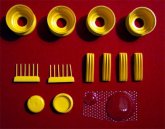
| The engines are airbrushed with Model Master Steel then the crankshaft bodies
and outside edges are done with Gunze-Sangyo Burnt Iron. The front gear housing
is painted dark gray and individual details are picked out the flat red, brass
and black enamels. Once the paint has dried the entire assembly is washed with a
black sludge wash. The insides of the cowlings are painted Model Master Drab
Green on the front half and flat black on the back half. The engine faces are a
little snug fitting into place so I sand the outside edge of each facing a
little to smooth out the fit. Each facing is secured with drops of medium
superglue placed on the backside. |
|
Back to the wings. The face of each nacelle where and engine will be mounted is
painted flat black. The engine mounting stubs are trimmed up and the engine
faces were test fit before being inserted into the cowlings. A second coat of
putty is applied to the exterior bomb rack mounting holes and this goes back to
the drying shelf.
|
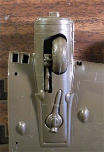
Let’s take a look at some landing gear for a few minutes. I’ve already cut
off the retraction arms and cleaned up those connection points and the seams on
the tires have been sanded down. The tires are airbrushed flat black and the
struts are done in flat aluminum. Once the
black has dried I mask the tires off
with regular masking tape, cut out the center sections with an Xacto and
airbrush the hubs flat aluminum. There is an odd tank on the gear strut, I
don’t know what it’s supposed to be but what the heck, let’s paint it red.
The wheels are glued to the struts and everything gets sludge washed and these
get set aside. There are lots of subassemblies starting to accumulate now. I
think it's time to go back to the wing/engine assembly again.
|
|
Each shaft stub gets trimmed and sanded so it will spin freely then the first
engine/cowling assembly is test fit. It doesn’t fit. The flap area on the
resin cowling is too thick to fit over the nacelle fairing. I use my Dremel with
the sanding drum in place to grind a 45 degree angle around the perimeter of the
nacelle and test fit the cowling again, much better
|
While test fitting the cowlings I check the fit of each propeller shaft also.
The outboard shafts fit wonderfully but the inboard shafts on each wing feel
sloppy and I think this will allow the propeller to droop when complete so for
these two positions a .01 piece of sheet styrene is glued to the front of each
mounting stub to tighten the fit. A heavy bead of medium super-glue is laid
around the beveled edge of the nacelle and around the lower area of the
engine-face mounting stub. Care is taken to not get any glue where the propeller
shaft will ride. There is a little slop in the cowling fit as far as rotation is
concerned which is good because as I look at the cowling from the front it needs
to be twisted a little to line the engine up correctly. The cowling assembly is
held in place and a drop of accelerator is placed into the cowl flaps and
allowed to run down the glue bead. |
Click on
image below to see larger image
|
 |
|
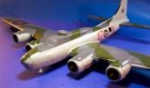
Each engine assembly is now packed with tissue paper and the wings get a coat of
Model Master gray primer. A few spots show up around the sides of the cowlings
that will need a little more sanding but overall they look pretty good. When I
built the “Impatient Virgin” from the Monogram B-24J kit I had a similar
problem in the exact same area.
The crew figures have arrived from Derwin and he did me real nice. He sent me
four of the original Pro-Modelers figures and a couple other various seated
pilots. I’m using both of the waist gunner figures, the standing gunner is
fine as designed but the crouched gunner needs a little adjustment. I want this
guy looking out the waist window rather than holding a gun so one arm is raised,
the gloved hand is cut off and repositioned. I’m using another standing figure
from the B-24J kit for the navigator. This one is too tall but I can cut off his
feet and it will not matter for the interior placement I have in mind. All the
crew are done with Flat Sea Blue with details done in flat yellow, light gray,
silver, black, dark gray, and olive drab. After the basic paint job is finished
they are washed with a black wash then dry brushed with a medium flat blue then
dull coated with Polly Scale clear flat.
To get the waist gunner positioned properly I hold the crouched crewmember in
place and mark the inside of the fuselage with a pen where their feet make
contact then hit each mark with a burr bit in the Dremel to make a slight notch.
The standing gunner will be manning a browning but I do not want to install the
guns until the final stages of assembly. I take one browning assembly and secure
it in place with a thin strip of masking tape then position the crewmember and
make mounting notches for him in the same manner as the other gunner. Now the
browning can be removed for later installation.
Matt
|